Z-Core: Performance Analysis
Benchmarking Z-Core — DOOM FPS across cache configurations, then CoreMark/MHz, STREAM and pointer-chase results.
A two-player digital bingo game taken all the way from synthesisable Verilog to a fabrication-ready GDSII layout on the open-source SkyWater sky130 process.
BinGo is a digital bingo game I took all the way from RTL to a fabrication-ready GDSII layout, using only open-source tools. The game itself is not new: I first built it out of 74LS-series logic chips for a university project. This time I rebuilt the exact same system at the integrated-circuit level on the SkyWater sky130 open PDK, which shrinks it by roughly 300,000× and clocks it at 50 MHz.
The point was to walk the complete digital flow end to end: write the Verilog, push it through synthesis and place-and-route, and come out the other side with a clean, signed-off chip. This page covers how the game plays, the hardware behind it, and the final layout.
Two players share one board. Before a game starts, each enters eight two-digit numbers on a
3×4 matrix keyboard. The keyboard controller scans the rows one at a time
and decodes each keypress through a small lookup table, with a 16 ms debounce
filter so a single press never registers twice. Each digit shifts through a pair of 4-bit
cascade registers, so two presses assemble one two-digit number, which is then written into a
16-entry by 8-bit memory. Sixteen numbers later, eight per player, pressing
the # key flips the design into play mode.
From then on, each press of the next button draws a number. The draw comes from
an 8-bit linear-feedback shift register whose primitive polynomial
(x⁸ + x⁶ + x⁵ + x⁴ + 1) gives a maximal-length sequence of 255 states before it repeats.
The raw bytes run 0 to 255, but a bingo number is two decimal digits, so each nibble is
BCD-corrected on the way out and the displays always read 00 to 99. There is
also a hack mode for debugging: flip a switch and a number set on eight DIP switches is fed in
instead of the random one, which makes it easy to force a specific draw.
Everything during play is coordinated by a nine-state machine. It sits idle
until the game starts (E0), then waits for a draw (E1). When next is pressed it
latches the drawn number (E2) and walks the memory one entry at a time (E3 and E4), comparing
each stored number against the draw. On a match (E5) it marks that slot and sets the matching
bit for that player (E6 or E7, selected by the top address bit). The 16-bit
game_state register is really two 8-bit bingo cards, one per player. The moment
all eight bits of either card are set, the machine stops in its endgame state (E8) and lights
the winner. If a scan runs off the end of memory without completing a card, it returns to E1
and waits for the next draw.
On the output side, four 7-segment displays show the numbers as you go: two for the value being entered, two for the number just drawn. A ten-LED bar shows the game state, multiplexed between the two players once a second so one bar can stand in for both cards, and it settles on the winner once the game ends.
The physical implementation runs through librelane on the sky130 PDK: Yosys for synthesis, OpenROAD for floorplanning, power distribution, placement, clock-tree synthesis and routing, then Magic and KLayout for the final GDSII and the DRC and LVS checks. The whole design is one 50 MHz clock domain, a 20 ns period.
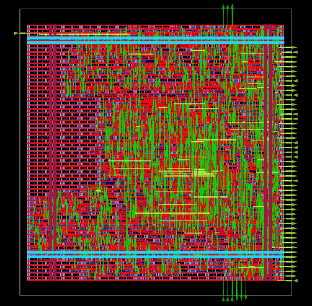
The signed-off design is 2,327 standard cells on a 39,731 µm² die (about 0.04 mm²), at roughly 59% core utilisation, drawing around 1.47 mW. It closes timing with 4.7 ns of setup slack to spare, so there is real headroom above 50 MHz, and it comes out DRC- and antenna-clean with zero violations. To confirm synthesis did not change the meaning of the design, I also ran gate-level simulation on the final netlist.
All of the RTL, testbenches and the librelane flow are on GitHub ↗.